
 EN
 English
 русский
 简体中文


Choose mineral concentration equipment by ore mineralogy, feed particle size, and the true cost per ton of concentrate, not by the purchase price of the machine. A forced-air flotation bank gives you stable froth on large cells, a self-aeration machine saves energy on smaller duties, and a center-driving concentrator with correctly selected rake torque protects your water balance from the first day of operation. This guide comes from the perspective of a manufacturer that has built flotation, grinding, classification, mixing and thickening lines for copper, gold, zinc, phosphate, potash and lithium projects. It explains what each equipment group must achieve, which selection mistakes raise operating cost, and what to verify before you place an order.
What mineral concentration equipment must actually achieve
A concentration plant has one job: reject gangue and upgrade the valuable mineral into a concentrate that a smelter, a leach circuit, or a direct market can accept. The equipment used in that line determines more than the final grade and recovery. It sets the water consumption, reagent consumption, energy demand, and the number of operators needed to keep the plant stable.
The whole flowsheet behaves like a chain. Grinding sets the liberation size. Classification stabilises the particle size going forward. Conditioning prepares the mineral surface for collection. Flotation does the actual separation. Thickening and dewatering recover the water and densify the concentrate bed. If one link is designed with the wrong tolerance, the rest of the chain pays for it. A thickener that is undersized for the tailings flow will force the plant to cut feed. A flotation machine with the wrong impeller type will develop a froth stability gap that reagent changes cannot fix.
These points explain why plant owners should define the ore over its full life-of-mine range, not the average grade. Equipment sized for the average is often too small in the first high-clay or high-fines period, and that period is exactly when the hardest operating conditions arrive.
| Performance driver | Typical plant target | What happens when it is ignored |
|---|---|---|
| Recovery rate | 85–95% for base metal sulphide ore | Valuable mineral leaves with tailings; revenue loss repeats every operating day |
| Concentrate grade | 18–25% Cu, 40–60 g/t Au, 45–55% Zn depending on ore type | Smelter penalties and higher freight cost per payable ton |
| Equipment availability | Above 90% including planned maintenance | Unscheduled downtime is usually the largest hidden cost in a plant |
| Energy consumption | 18–30 kWh per ton of ore through grinding and flotation | Power is the biggest controllable variable cost for most owners |
| Water recovery | 70–85% of process water recovered from thickener overflow | Fresh water shortage stops production, especially in arid regions |
The five equipment groups in a concentration plant
Although every flowsheet is different, a typical concentration plant contains the same five groups of equipment. Understanding each group’s function helps a buyer compare bids that normally look like long lists of machine names and model numbers.
Flotation machines
Separate hydrophobic valuable minerals from gangue in a pulp of controlled density and reagent chemistry. The family includes self-aeration types SF, BF and JJF, and forced-air types XCF/KYF and CLF.
Selection priority: ore type, feed particle size, cell volume, and whether the cell serves a roughing, scavenging or cleaning stage.
Thickeners and concentrators
Continuously dewater slurries by gravity settling and return clear overflow to the process. The center-driving concentrator is the standard choice for medium and large plants.
Selection priority: solids loading rate in tons per square meter per day, required underflow density, settleability of the mineral, and flocculant regime.
Spiral classifiers
Split a ground product into sand and overflow by settling in an inclined spiral trough. The sand return closes the grinding circuit; the overflow becomes flotation or gravity feed.
Selection priority: cut size, feed solids concentration, tank length, spiral diameter and pitch.
Mixing tanks
Condition pulp with reagents, dilute concentrated streams, and hold slurry at a controlled density. Types include slurry mixing tanks, agent mixing tanks and high-concentration XBN tanks.
Selection priority: pulp density, retention time, impeller power, and freedom from dead zones where reagent mixing becomes ineffective.
Wet grinding ball mills
Reduce ore to the particle size that liberates the valuable mineral. The wet grid-type ball mill is the common choice for plants that need a dense, uniform discharge for classification.
Selection priority: ore work index, feed size, target P80, throughput and discharge arrangement.
Beyond these five, feeding equipment such as a channel-type feeder or disc feeder controls the ore entry into the first mill stage. It sounds minor, but irregular feeding causes surging in the grinding circuit, and surging ruins flotation stability.
Flotation machine selection: airflow, mechanism and duty
Flotation is the main separation tool in most concentration plants. The machine must disperse air, suspend the mineral particles, create a froth zone stable enough to carry the mineral up to the launder, and keep pumping energy in a reasonable range.
Self-aeration machines draw air into the pulp by the rotating impeller. They have no blower, less pipework and simple operation, and they work well in cells across the small and medium volume range. SF, BF and JJF all belong to this class. Forced-air machines like XCF/KYF and CLF receive air from a low-pressure blower. The result is deeper tanks, more uniform air distribution, and a froth layer that stays stable even when the feed grade changes quickly. In large rougher and scavenger banks, that stability is worth the added blower cost.
| Machine type | Aeration | Typical duty | Strengths | Practical caution |
|---|---|---|---|---|
| SF | Self | Rougher and cleaner in small and medium plants | Simple structure, easy start-up, strong circulation | Less efficient when cell volume becomes very large |
| BF | Self | Rougher, scavenger, coarse particle feed | Handles high-density slurry without sanding | Finer air control is limited compared with forced air |
| JJF | Self | Rougher and scavenger | Self-aspirating, low operator attention, low power | Needs a stable pulp level to avoid under-frothing |
| XCF/KYF | Forced | Rougher, scavenger, cleaner in large cells | Stable froth, uniform air dispersion, deep tanks | Requires blower, air control valves and additional pipework |
| CLF | Forced | Coarse particle flotation at high pulp density | Specially designed to lift coarse heavy particles | Higher installed power on the drive side |
| GF | Self | Coarse particle flotation in smaller cells | Low energy per cubic meter, simple mechanism | Generally limited to smaller cell volumes |
In our own installations, the XCF/KYF combination is a common choice for large rougher and scavenger duties. The XCF single-sided paddle cell pairs with the KYF cell of the same volume, and the two share one air supply and one launder. This arrangement shortens the bank length, simplifies floor layout and reduces the laundered area that has to be cleaned.
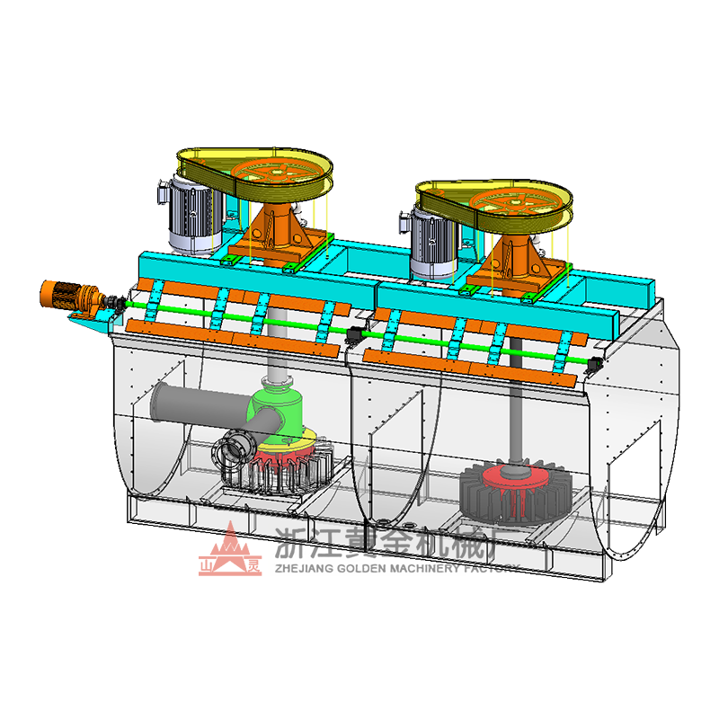 XCF/KYF Flotation Machine for Coarse-Grind and Rougher DutiesThis combined XCF suction and KYF direct-current cell pair shares one air supply and launder, offering low energy use and reliable suspension for coarse heavy particles.View Product →
When the ore carries a coarse grind product, BF or CLF cells are often better because they keep coarse heavy particles in suspension without building a sand bed. One of the first questions to ask a supplier is whether the proposed cell has actually handled this ore type and this particle size range before.
Thickeners: water recovery and underflow control
The center-driving concentrator is the workhorse of dewatering in mineral concentration. Slurry enters the central feed well, solids settle to the bottom, a rotating rake drags the settled bed toward the center discharge, and clear overflow spills over the rim. The big number to watch is the rake torque. A rake that is chronically overloaded wears the gearbox, bends the shaft and eventually stops the plant.
Thickener sizing is normally expressed as solids loading: tons of dry solids per square meter of tank area per day. For a concentrate or tailings stream that settles well, 0.5–1.5 t/m²/day is a practical range. For fine clay-bearing tailings, the number can be much lower, sometimes below 0.3, and flocculant consumption becomes the controlling factor.
Underflow density is the second number. In base metal plants, 55–65% solids by weight is common for a thickener feeding a filter, and 45–55% for a tailing dam feed. The pump and pipes must be sized for the actual underflow viscosity, especially when the mineral is highly flocculated and the bed behaves like a soft solid. Getting the underflow density right also decides how much water you recover. With clean overflow and a well-controlled bed, the plant can routinely return 70–85% of its process water. In salt-lake potash projects, where brine is both the medium and the valuable liquid, a small water balance error turns into a large production loss. The thickener design has to account for brine density and temperature from the first calculation.
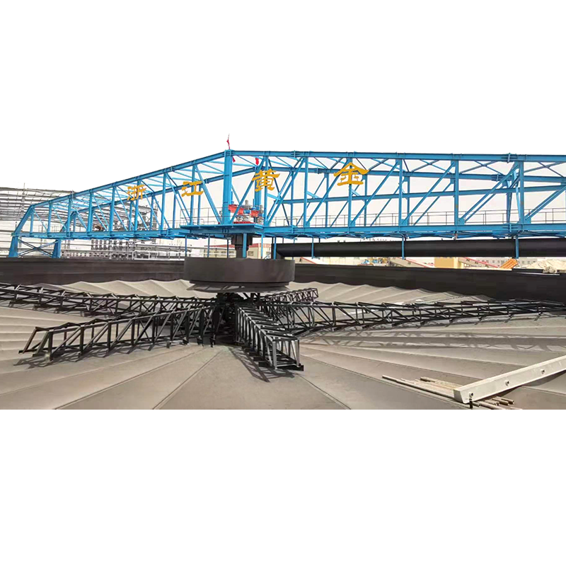 Central Driving Concentrator for Efficient Water RecoveryThis thickener raises solids from 20-30% to 40-70%, with a lifting rake mechanism and torque protection to manage high-density underflow and recover process water.View Product →
Grinding and classification: particle size decides everything downstream
No flotation cell can recover a mineral that has not been liberated. Grinding is the step that creates the particle size distribution. The wet grid-type ball mill is a standard choice in small and medium plants because it feeds a dense pulp to the classifier and handles a high circulating load with good control of the discharge size.
The spiral classifier works in a closed circuit with the ball mill. Oversize sand returns to the mill for another pass; overflow moves on to flotation. For flotation feed, the target is often 60–75% passing 74 microns, but the right number comes from liberation testing, not from a default. A coarse-grained ore might be perfectly liberated at 80% passing 150 microns; a fine-grained or disseminated ore could require 80% passing 45 microns. Grinding finer than liberation costs energy with no recovery gain, and overgrinding creates fine slime that consumes reagents and drags down the concentrate grade.
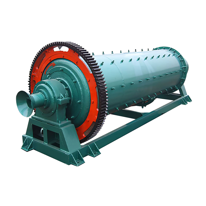 Wet Grid Ball Mill for Closed-Circuit GrindingThis mill feeds a dense pulp to the classifier and handles high circulating loads with a 15% higher capacity than overflow mills, suitable for liberation testing.View Product →
The classifier must also hold the cut size under variations in feed hardness. In practice, we recommend a screen check every shift for the first weeks after commissioning. Operators can then correlate small changes in overflow size with flotation recovery before the deviation becomes serious.
Mixing tanks: the conditioning step that gets underestimated
Conditioning time is one of the cheapest process variables to change and one of the most common causes of a flotation problem when it is wrong. Reagents need time to react with the mineral surface. A slurry mixing tank provides that time before the pulp enters the first flotation cell. An agent mixing tank dissolves and homogenizes reagent doses; if it is too small, the reagent concentration fluctuates and the downstream flotation cells become impossible to control.
Two design points matter most. The first is dead zones. A big tank with a small impeller appears to mix, but the core of the pulp volume may stay untreated and then short-circuit to the flotation feed. The second is power input per unit volume. Too little power gives incomplete suspension; too much creates strong shear that can strip reagent layers or break bubbles. Plant experience shows that this problem is more common than operators believe, because the tank looks active while the bottom and corners keep stagnant pulp.
The XBN high-concentration mixing tank is a variant designed for pulp densities that ordinary mixing tanks cannot handle. It keeps solids moving and avoids the local concentration spikes that change the reagent-to-solids ratio during flotation. For plants treating high-density leach pulps, this unit is worth studying before a generic tank is selected.
How ore type changes the equipment list
Mineral concentration equipment cannot be selected without knowing the chemical and physical behaviour of the ore. Two plants that both float copper look similar on paper, but if one treats massive sulphide and the other oxide-carbonate ore, the flotation machine duty, grinding target and dewatering system all change. The table below summarizes the typical logic for six common ore families.
| Ore family | Flotation approach | Grinding approach | Thickening approach | Main risk |
|---|---|---|---|---|
| Copper-gold sulphide | XCF/KYF rougher-scavenger, cleaner for final concentrate | Wet grid ball mill with spiral classifier | Center-driving concentrator on concentrate and tailing | Coarse free gold building up in the circulating load |
| Lead-zinc sulphide | Sequential flotation with SF or BF cells, lead first then zinc | Fine grind around P80 75–100 microns | Separate thickeners for each concentrate | Pyrite depression failure contaminating both concentrates |
| Gold oxide | Gravity for free gold, flotation only for a sulphide proportion | Rod mill or ball mill avoiding overgrinding | Thickener ahead of the leach feed | Slime generation consuming cyanide and gold losses in solution |
| Potash and salt lake brine | KCl flotation in saturated brine | Crusher and rod mill for soft salt rock | Large thickeners and mixing tanks in brine service | Corrosion, scaling and crystallisation |
| Phosphate rock | Fatty acid direct flotation or reverse flotation | Rod mill or ball mill for coarse liberation | Center-driving thickener for tailing and water | Slime interference and a strong effect from temperature |
| Spodumene lithium | Flotation after scrubbing, desliming and reagent conditioning | Ball mill after roasting if needed | Thickener before flotation feed | Slime coating that depresses the mineral surface |
The table is not a design manual. It is a reminder that the same equipment category appears everywhere, but the operating point inside that category must be set by the ore. That is why our engineers ask for a full mineralogical description, not just a metal grade, when a customer requests a quotation.
Where operating cost goes, and how to reduce it
Energy is the single largest controllable cost faced by the owners of concentration plants. Measured at the equipment level, a typical electrical energy split looks like this.
Typical electrical energy share in a flotation-based concentration plant
Reducing the absolute number starts with the grinding feed size. A crusher product that is 10 mm finer can cut the ball mill energy demand by roughly 5–8% because the mill no longer uses its charge to repair the last crushing stage’s mistake. After that, the following measures are practical for an existing plant:
- Install variable frequency drives on flotation machine impellers and run them at the lowest speed that keeps particles in suspension.
- Keep the froth depth at the design value. Pulling froth with an over-energetic air supply raises energy per ton and lowers grade.
- Add a froth crowder to accelerate the mineralized froth into the launder without raising the air rate.
- Automate thickener underflow control. A stable bed means less flocculant per ton of dry solids and a steadier return-water flow.
- Monitor the classifier overflow size. An over-ground product costs grinding energy and reagent, and it produces a concentrate that is harder to dewater.
Energy is not the only operating cost. Wear parts, steel grinding media and flotation reagents are all sensitive to equipment choice. A flotation impeller for abrasive ore is usually better at a slightly lower tip speed. A thickener rake drive with the correct torque setting avoids shear wear. A classifier spiral that runs at the correct inclination sends the right size split to flotation instead of sending sand that buries the cell bottom. Every one of these points shows up in the monthly cost statement of the plant.
Maintenance: faults that force production stops
Concentration equipment runs in a slurry with 30–70% solids by weight. Abrasion and scale are the main enemies, and once a breakdown happens, the plant feed stops. The tables below are a practical summary of the faults that field engineers see most often on flotation and thickening machines.
| Symptom | Likely cause | Practical fix |
|---|---|---|
| Froth is thin and carries no mineral | Air rate too high, reagent line blocked or pump under-dosing | Reduce air at the valve, check the reagent line and dose rate |
| Froth forms but does not move to the launder | Froth depth too deep, launder clogged | Open the dart valve or raise the weir, clean the launder |
| Recovery drops suddenly | Feed size change, pulp density change, reagent ratio lost | Check classifier overflow and flotation feed density first |
| Power draw creeps upward | Impeller or stator worn, slurry filling the mechanism | Inspect the wear pair and replace before the gap grows too wide |
| Pulp level unstable | Level sensor fouling, dart valve actuator stroke changing | Clean the sensor, calibrate the stroke, inspect the actuator |
| Symptom | Likely cause | Practical fix |
|---|---|---|
| Rake torque rising fast | Feed density too high, bed compacted | Raise the rakes, reduce feed rate, increase underflow pump speed |
| Overflow cloudy | Flocculant under-dosed, feed rate above capacity | Increase flocculant dose, lower feed rate, inspect the feed well |
| Underflow too thin | Bed not built, flocculant overdosed | Reduce flocculant, build bed depth slowly, control density |
| Seal water leaking | Seal pressure wrong, gland worn | Adjust seal water, rebuild the gland, replace packing |
| Gearbox noise | Low grease, misalignment, overload history | Regrease, check alignment, inspect the torque limiter |
Spare parts inventory is part of maintenance. For a small plant, carrying one complete impeller-stator set for each flotation model, one set of thickener rake wear shoes, and standard rubber spares for the classifier is usually the right balance between cost and safety.
What recent plant projects show
Equipment choices look different when they are attached to a real project. In a 1-million-ton-per-year copper-gold pyrite project in Anhui, the line combines a wet grid ball mill, a spiral classifier and XCF/KYF flotation machines in rougher and scavenger banks. The copper and gold minerals are locked in pyrite at a moderately coarse grain, so the design keeps the primary grind at a point where the pyrite is not over-milled and the recoverable gold is not stranded in a slime fraction.
A different example is a potash project in Laos, built around large mixing and thickening equipment. The plant operates in saturated brine, so corrosion margins and a conservative thickener diameter were part of the selection logic. The equipment family is the same as a copper plant, but the design values for materials, drive torque and air handling are completely different.
The pattern is clear: every successful plant starts from the ore and works backward to the machine. The details on how to choose mineral concentration equipment according to ore type are covered in a separate technical article.
A practical checklist before ordering
Buyers who work through this checklist before comparing quotations save more money in one month of plant operation than they typically negotiate on the equipment price.
Feed and product data
- Head grade, ore type, and grade variability over the mine plan
- Liberation size from mineralogical analysis
- Throughput in metric tons per day
- Slurry density, pH and temperature ranges
Flotation specifics
- Cell volume per bank and total residence time
- Impeller speed options and motor power
- Air rate range and blower capacity needed
- Froth launder design and froth depth control method
Thickener specifics
- Tank diameter and unit area per ton per day
- Rake torque and lift system
- Underflow pump type and density instrumentation
- Flocculant dosing system and tank configuration
After-sales and deliverability
- Reference list in the same ore family
- Availability of impellers, stators, rakes and liners
- Installation, commissioning and training support
- Ability to deliver the whole concentration line if required
The last item is more important than most buyers expect. A supplier that can coordinate the ball mill, classifier, flotation machines and thickener as one engineered line reduces interface mistakes. Flange sizes, launder heights, pump head requirements and control signals all connect. When each machine comes from a different source, the plant owner becomes the integrator by default.
Frequently asked questions about mineral concentration equipment
What is the difference between a thickener and a concentrator?
In daily plant language the two terms are used for the same machine: a gravity settling tank that raises the solids concentration of a slurry. “Concentrator” is also used for the whole plant building, so operators usually say “thickener” when they mean the machine. In this article, a concentrator refers to a center-driving thickener in a dewatering role.
Should I choose a self-aeration or a forced-air flotation machine?
For cell volumes up to about 8–10 cubic meters, self-aeration machines such as SF, BF and JJF are simple, energy-efficient and easy to operate. For larger cells, forced-air XCF/KYF machines give better air distribution and froth stability. Many plants use both in one flowsheet: XCF/KYF for large rougher and scavenger banks, and a small self-aeration cell for a coarse particle stream.
What is a normal underflow density from a center-driving concentrator?
For base metal concentrates, 55–65% solids by weight is common before filtration. For tailings, 45–55% is typical. The actual number depends on mineral density, particle size distribution and flocculant regime, so a settling test with a real ore sample is recommended before the tank is sized.
How much water can a thickener recover?
With proper flocculant dosing and a stable bed, overflow recovery is typically 70–85% of the process water in a flotation plant. In a brine or salt-lake operation, this percentage is critical because the liquid phase is also a product stream.
What is the most common cause of a sudden flotation recovery drop?
In our experience, the most frequent cause is a change in the feed particle size distribution, followed by a change in pulp density at the flotation feed. Operators should check the classifier overflow size and the feed density before adjusting reagents.
How often do flotation impellers and stators need to be replaced?
For abrasive sulfide ore, the wear pair typically lasts 6–12 months, depending on impeller tip speed and the amount of fine abrasive material in the pulp. An inspection every quarter and a lower warning threshold on power draw are recommended. Replace the pair together; a new impeller with a worn stator does not restore performance.
Can the same flotation machines process different ore types over time?
Flotation machines are flexible, and many plants switch between ore blends by changing reagents and grind size. The recovery and concentrate grade will change with the ore. For long-term flexibility, size the mechanisms, air supply and launders for the most difficult ore, not the easiest one.
Mineral concentration equipment stops being a list of machine names as soon as it is connected to an ore body and a target concentrate. The right plant starts with the ore characteristics, works through grinding, classification, conditioning, flotation and thickening, and finishes with a purchasing decision that includes operating cost and after-sales support. If you are planning a new concentrator or upgrading an existing one, provide the feed data first and let the equipment selection follow the ore. That is the difference between a plant that looks correct on paper and a plant that holds its recovery in the third month of continuous operation.


