
 EN
 English
 русский
 简体中文


Inside a CIL Leach Tank: The Six Parts That Decide Carbon-Gold Contact
A carbon-in-leach tank is not a stirred pot with carbon thrown into it. It is a baffled, aerated, slow-turning reactor in which three events must occur in the same cubic metre of pulp at the same time: cyanide dissolves gold from the ore surface, dissolved oxygen keeps that dissolution moving, and activated carbon adsorbs the gold-cyanide complex quickly enough to beat the gangue minerals that would otherwise steal it. Every mechanical detail inside the shell exists to keep those three events happening together, and every one of them can be the reason a plant misses its recovery target.
Impeller and shaft
Axial-flow hydrofoil or pitched-blade turbines run at 3 to 5 m/s tip speed and draw roughly 1 to 3 kW per m³. The duty is not only to keep solids off the bottom but to hold 6×12 mesh carbon in full suspension so it can load gold evenly instead of settling into dead zones.
Draft tube
A central tube guides upward flow and forces a defined top-to-bottom turnover. In air-lift designs the sparged air itself becomes the pumping motive force, which cuts power draw but makes the tube geometry far less forgiving of a wrong diameter.
Baffles
Four vertical baffles at roughly one-tenth to one-twelfth of the tank diameter break the rotating swirl and convert it into vertical circulation. Remove them and the pulp spins as a plug; carbon stratifies by size, and residence time becomes guesswork.
Air sparge ring
A perforated ring or sparger beneath the impeller delivers air at about 0.5 to 1.5 Nm³ per hour per cubic metre of pulp. Oxygen is a reactant in the cyanide leach, not an optional extra, and the impeller has to disperse it rather than let it channel up the shaft.
Carbon retention screen
Interstage sieve bends, cylindrical screens or linear-motion screens with 0.8 to 1.5 mm apertures keep carbon in its stage and let pulp through. Twenty to thirty percent open area is a working target; below that, head loss climbs and the stage starts to flood.
Overflow launder and cone bottom
The launder fixes the pulp level and feeds the next tank by gravity. A 60° cone bottom drains cleanly during shutdown; a flat bottom saves steel and then costs a week of manual desanding every time the circuit stops with solids still in it.
The practical consequence is simple: a CIL tank is sized by chemistry but it fails by mechanics. When a plant reports that carbon is "not picking up gold", the root cause is more often a settling zone, a blinded screen, a bent shaft or an air line that has quietly blocked than a fault in the ore or the reagent dosing.
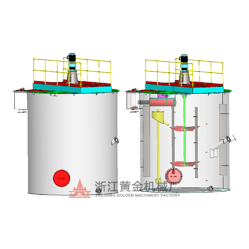 Mechanical Mixing Leach TankMechanical stirring leach tank for hydrometallurgical leaching and related processes, selected by particle size, leaching time, slurry ratio, and stirring intensity.View Product →
How Pulp Travels Through a CIL Tank Train
Pulp enters the first tank, cascades by gravity through the launder into the second, and continues through six to twelve tanks in series. Total retention in a CIL circuit usually lands between 20 and 30 hours, which works out at roughly 3 to 5 hours per tank. The cascade works because the tanks sit on a stepped foundation with 300 to 500 mm of free fall between stages; get that fall too small and pulp backs up, get it too large and you aerate the launder instead of the tank.
Gold tenor in solution falls steeply along the train, and the shape of that fall tells you whether the circuit is healthy. A normal profile looks like this:
If tank 4 still carries 3 mg/L while tank 6 carries 2.5 mg/L, the tail of the train is doing no work and the circuit is short-circuiting. That pattern is almost always mechanical: coarse solids bypassing around a screen, a dead zone under a badly placed sparger, or carbon that has stopped moving between stages.
Carbon runs the other way. Fresh or regenerated carbon is added to the last tank, airlifts or transfers move it one stage upstream every 12 to 24 hours, and loaded carbon is washed out of the first tank at 2,000 to 7,000 g/t before going to elution. Because carbon and pulp move in opposite directions, the carbon always meets the richest solution in the tank where gold tenor is highest, and the freshly leached pulp meets the cleanest carbon in the last tank. That counter-current arrangement is what lets a well-run circuit push recovery past 92 to 95 percent on free-milling oxide ore.
Carbon inventory matters as much as carbon grade. At a typical 10 to 25 g/L of pulp, a 100 m³ working volume holds 1 to 2.5 tonnes of carbon per stage, so a six-tank train carries 8 to 15 tonnes. Losing half a tonne a month to screen failures and pump damage is a five-figure annual cost that never appears in a recovery report.
CIP and CIL: The Same Tank Shell, a Different Job
In a CIP circuit the leaching is finished before the carbon arrives. Four to eight leach tanks with cyanide and air do the dissolution, and the adsorption tanks that follow hold carbon and nothing else. In a CIL circuit the carbon sits in the leach tanks themselves, so dissolution and adsorption compete for the same gold ions in the same vessel. That single difference drives almost every subsequent design decision, from tank count to carbon consumption.
| Design point | CIL circuit | CIP circuit |
|---|---|---|
| Where carbon sits | Inside the leach tanks, suspended in pulp | In dedicated adsorption tanks after leaching |
| Typical stage count | 6 to 12 combined leach-adsorption tanks | 4 to 8 leach tanks plus 4 to 6 adsorption tanks |
| Total retention | 20 to 30 hours | 24 to 48 hours across both sections |
| Behaviour on preg-robbing ore | Favourable, carbon competes with the mineral for gold | Unfavourable, gold is lost to the ore before carbon is added |
| Carbon condition | Exposed to cyanide, lime and full pulp, so fouling and attrition are higher | Cleaner pulp, less blinding of carbon pores |
| Capital cost | Lower, fewer tanks and less transfer equipment | Higher, more tanks, screens and piping |
| Control difficulty | Harder, carbon and leach chemistry interact | Easier, the two duties can be tuned separately |
| Usually preferred for | Slow-leaching, sulphidic or mildly preg-robbing ore | Fast-leaching oxide ore with clean, well-liberated gold |
The comparison is not about which process is better in the abstract. It is about how fast your ore releases gold and how aggressively your gangue tries to take it back. An ore that leaches in four hours gains little from CIL and pays for it in carbon attrition; an ore that needs thirty hours, or one containing carbonaceous material that adsorbs gold from solution, will lose several percentage points of recovery in a CIP circuit no matter how well the adsorption section is operated.
Mixing, Air and Oxygen: The Three Inputs That Decide Recovery
Agitation has to suspend, not just stir
The classical target is the just-suspended speed, the impeller rpm at which no particle stays motionless on the bottom for more than one to two seconds. Run below it and coarse solids build a bed in the cone, taking gold and carbon with them. Run far above it and you buy nothing except shaft fatigue, higher power draw and more carbon attrition against the impeller and baffles. In practice, most CIL tanks sit at 1.1 to 1.3 times the just-suspended speed, which lands at 1 to 3 kW per m³ for typical 40 percent solids pulp.
Air is a reagent with a flow meter
Cyanide leaching consumes oxygen, and cyanide itself is oxidised to cyanate if the conditions drift. Dissolved oxygen measured at the tank outlet should stay above 5 mg/L, and most well-run circuits target 6 to 8 mg/L. Below 4 mg/L, leach kinetics fall off sharply and the carbon simply waits for gold that is not being released. Air sparging also strips hydrogen cyanide if pH is allowed to drop, so pH control at 10 to 11 with lime and adequate oxygen are managed together, never separately.
Baffles and sparger position decide the flow pattern
A sparger sitting directly under the impeller gives good gas dispersion but poor top-to-bottom turnover. A sparger placed inside a draft tube gives strong circulation but risks gas locking if the air rate runs too high. The reliable arrangement for a carbon tank is a central draft tube with the sparger inside it, four baffles on the wall, and a clearance between impeller and bottom of 0.3 to 0.5 times the impeller diameter.
 Customizable XB Type Slurry Mixing TankCustomizable slurry mixing tank that keeps ore particles suspended and contacts them with reagents before flotation and similar separation operations.View Product →
Sizing the Tank: Pulp Density, Retention Time and Working Volume
Almost every sizing error in a leach circuit traces back to mixing up slurry volume with solids tonnage. Work the numbers in this order and the tank dimensions fall out with little room for argument.
- Take the dry solids feed, for example 500 t/d.
- Divide by the solids fraction by weight, for example 40 percent, giving 1,250 t/d of slurry.
- Divide by slurry specific gravity, typically 1.40 to 1.50 at that density, giving about 860 m³/d of pulp.
- Multiply by the required retention time, for example 24 hours, giving 860 m³ of working volume.
- Divide by the number of stages, for example eight, giving roughly 108 m³ per tank.
- Add 10 to 15 percent freeboard above the pulp level and the cone volume beneath it.
At a height-to-diameter ratio of 1.2, that 108 m³ working volume corresponds to a tank about 4.8 m in diameter with a 5.8 m straight side. Push the same duty to 50 percent solids and the slurry volume drops by roughly a fifth, which looks like a saving until you discover that the agitator now needs noticeably more torque and the carbon struggles to stay dispersed in the heavier pulp.
Two rules of thumb keep engineers out of trouble. First, never design the last stage for less than three hours of retention; the final tank carries the lowest gold tenor and needs time to reach the tail value. Second, keep the ratio of tank diameter to impeller diameter between 2.5 and 3.5. Outside that band, either the impeller is too small to move the whole volume or the tank is too narrow to develop a stable circulation loop.
 XBN High Concentration Mixing TankHigh-concentration mixing tank for slurries up to 70% solids and particles under 1 mm, with enlarged propeller and circulating cylinder for strong mixing.View Product →
Carbon Management Inside the Tank
Activated carbon is the most expensive consumable in the circuit and the easiest thing to damage. The standard grade for gold recovery is coconut-shell carbon at 6×12 mesh, hard enough to survive thousands of transfer cycles and fast enough in kinetics to load in a few hours. Concentration in the pulp usually sits between 10 and 25 g/L. Higher concentrations shorten the loading time but increase attrition, screening load and the amount of carbon circulating through elution.
Loading along the train follows the same counter-current logic as gold tenor, but in reverse:
Three operating habits protect that profile. Advance carbon often enough that no single stage is asked to load more than about 1,500 g/t per cycle. Keep the interstage screens clean enough that the designed carbon concentration in each tank is actually the concentration you measure. And wash carbon with acid before elution when calcium or scale is present, because a carbonate crust on the surface blocks the pores far more effectively than the gold complex ever fills them. Regeneration at 650 to 750 °C in a rotary kiln restores most of the activity, and plants that track activity as a number rather than a feeling usually keep carbon in service for several years before replacing it.
Operating Parameter Reference for CIL and CIP Tanks
| Parameter | Typical range | What happens when it drifts |
|---|---|---|
| Pulp density | 35–45% solids by weight | Too thin wastes tank volume and cyanide; too thick starves the impeller and traps carbon |
| Retention per stage | 3–5 hours | Below 2.5 hours the last stage cannot reach tail tenor |
| Total circuit retention | 20–30 hours (CIL), 24–48 hours (CIP) | Short retention shows up as rising gold in tailings, not as a tank fault |
| Dissolved oxygen | 5–8 mg/L at outlet | Below 4 mg/L leach rate falls; above 10 mg/L cyanide loss to cyanate rises |
| pH in leach | 10.0–11.0 with lime | Low pH releases hydrogen cyanide and attacks carbon; high pH slows leaching |
| Free cyanide | 200–600 mg/L as NaCN | Underdosing leaves gold undissolved, overdosing raises cost and preg-robbing |
| Carbon concentration | 10–25 g/L of pulp | Low concentration shifts load onto the last tank; high concentration raises attrition |
| Impeller tip speed | 3–5 m/s | Low speed sands the cone, high speed grinds carbon to fines |
| Screen aperture | 0.8–1.5 mm | Too large loses carbon, too small blinds and floods the stage |
| Carbon loading at elution | 2,000–7,000 g/t | Overloading the carbon leaves gold in solution at the head of the train |
Troubleshooting: Eight Failures Seen in Real Leach Tanks
- Sanding in the cone. Coarse solids settle because tip speed fell after an impeller trim or because the sparger blocked and killed the air lift. Check power draw against the commissioning baseline before touching the ore blend.
- Carbon at the overflow. Either the retention screen has a hole, the pulp level is running above the screen top, or the flow rate has exceeded screen capacity. Screen aperture is not the problem in most cases; the pulp level is.
- Short-circuiting. Pulp moves from inlet to outlet faster than the design retention because baffles are missing or the inlet and outlet are too close. A tracer test settles the argument in an afternoon.
- Carbon fouling. Loading capacity drops even though fresh carbon is being added. Calcium carbonate, gypsum and oil from the mill circuit all block pores; acid washing and tighter oil control resolve it.
- Oxygen starvation at the bottom. Sparger holes plug with scale because the air is not dried or the ring sits in a slow-flow zone. Dissolved oxygen logged per stage exposes this long before recovery falls.
- Excess fines in carbon. Attrition rises when tip speed exceeds 5 m/s, when carbon is transferred through centrifugal pumps instead of airlifts, or when the carbon is simply too soft for the duty.
- Screen blinding. Wood chips, fibre and coarse mica peg the apertures. Washing screens with a low-pressure water line during each advance costs minutes and saves the stage.
- Vibration and shaft failure. Usually a build-up of solids on one impeller blade after a shutdown, or a critical speed hit during start-up. Barring the shaft and checking runout at every rebuild prevents most of it.
Two of these deserve special mention for gold circuits. On preg-robbing ore, half the battle is getting carbon into contact with dissolved gold before the carbonaceous matter does, so the first tank's mixing intensity and carbon concentration matter more than anything downstream. In the Solomon Islands concentrator renovation and expansion that followed the gold recovery upgrade route, the retention time and tank configuration were reworked rather than simply scaled, because adding tank volume to a circuit that is short-circuiting multiplies cost without multiplying recovery.
Materials and Mechanical Details That Cause Downtime
The wetted side of a leach tank lives in hot, alkaline, abrasive, chloride-bearing pulp, and that combination eliminates most shortcuts. Carbon steel shells with 3 to 6 mm of rubber lining or a properly applied epoxy system handle most gold circuits. Where chloride levels run high or the ore is treated with acid washes, 304 or 316L stainless becomes the cheaper option over a ten-year horizon even though the first invoice is higher.
The impeller is the component that decides maintenance cost. High-chrome castings last well in abrasive pulp, rubber-covered steel absorbs impact from tramp material, and 316L suits aggressive chemistry. The shaft needs a rubber or HDPE sleeve at the pulp line, because that is where corrosion fatigue starts and where most shaft failures begin. Gearboxes are usually sized for the starting torque with a full tank of settled solids; a gearbox chosen on running torque alone is a gearbox waiting to fail on the first power interruption.
Details that look minor on a drawing matter in the field. A drain valve large enough to empty the tank in a shift, an access manway above the pulp line, lifting lugs rated for the impeller assembly, and a launder with a removable cover so a blocked screen can be reached without scaffolding all fall into that category. Plants that buy on price alone usually discover these details during the first unplanned shutdown.
What to Specify When Ordering a Leach or Adsorption Tank
A clear inquiry gets a usable quotation. Vague ones get a tank shell with a guessed agitator, and the guess is always conservative, which means expensive.
- Dry solids throughput in tonnes per day, and the design and maximum values.
- Solids specific gravity and the target pulp density range by weight.
- Required retention time per stage and total number of stages.
- Particle size distribution, especially the top size and the fines fraction, which drive the just-suspended speed.
- Cyanide and lime dose ranges, pH window, and dissolved oxygen target.
- Carbon size, concentration and the loading expected at elution.
- Chemistry report covering chlorides, sulphates, and any acid wash planned for the circuit.
- Layout constraints: available footprint, headroom, foundation level and the required cascade drop.
- Power supply voltage and frequency, plus whether a variable frequency drive is intended.
- Site conditions, including altitude, ambient temperature and seismic classification.
One item is regularly forgotten and regularly expensive: the free cyanide concentration in the pulp. It changes the elastomer selection for linings and sleeves, and it changes the carbon grade recommendation. Another is the intended maintenance strategy. A plant that plans to inspect impellers every six months needs larger manways and better access than one that plans to run for two years uninterrupted.
For copper-gold and polymetallic circuits, the leaching tank rarely stands alone. The Anhui copper-gold pyrite project is a useful reference because the leach and adsorption stages had to be sized against a flotation concentrate rather than raw ore, and the pulp rheology from that concentrate drove the impeller selection more than the head grade did. Buyers comparing proposals should ask for the specific mixing calculation behind each agitator, not just the kilowatt rating.
Commissioning the Circuit: The First Thirty Days
Commissioning a leach train is mostly about water and solids before it is about gold. The sequence that avoids most early damage runs like this:
- Hydro-test every shell and launder before any lining is closed up, then re-check flange torque after the first warm day.
- Run each agitator in water for four hours, logging vibration, bearing temperature and motor current at the design level.
- Verify sparger air distribution by observing the boil pattern across the tank surface, not by reading the flow meter.
- Introduce solids at 15 to 20 percent and step up to design density over several days, watching cone pressure and impeller current.
- Add carbon only after pulp density is stable, then confirm the screens retain it at the design flow.
- Establish the sampling routine early: solution tenor and free cyanide at each stage, dissolved oxygen at each outlet, carbon concentration in each tank.
- Record the baseline vibration and power figures at design throughput; every later maintenance decision should be measured against that baseline.
The most common commissioning mistake is starting at full density on day one. Settled solids from a cold start can lock an impeller within seconds, and the resulting shaft damage delays the ramp-up by weeks.
Questions Buyers Ask Most Often
What is the difference between a leach tank and an adsorption tank?
A leach tank provides cyanide, oxygen and residence time so gold dissolves into solution. An adsorption tank provides contact between that solution and activated carbon so the gold complex is captured. In a CIL circuit both duties happen in the same vessel; in a CIP circuit they are separate vessels with different agitator duties and different screen arrangements.
How many tanks does a CIL circuit need?
Six to twelve stages is the working range. The count is set by retention time, by how many adsorption stages are needed to reach the target tail tenor, and by how much freeboard the site layout allows. Fewer than six stages usually means either a very fast-leaching ore or a recovery target that is being quietly missed.
What carbon size and concentration should be used?
6×12 mesh coconut-shell carbon at 10 to 25 g/L of pulp covers most gold circuits. Smaller carbon loads faster but screens harder and attrites faster; larger carbon screens cleanly but needs longer contact. The screen aperture is chosen to retain the carbon with margin, typically 0.8 to 1.5 mm.
Why does carbon collect at the bottom of the tank?
Because the impeller is no longer producing enough bottom velocity to keep it suspended. Causes include a blocked sparger, a worn impeller, a pulp density above design, or a tank that was restarted with settled solids. Adding more carbon to compensate makes the problem worse, because the extra inventory increases the settling load on the same insufficient flow.
How long does pulp stay in one tank?
Three to five hours per stage in a CIL circuit, which produces 20 to 30 hours in total across six to eight tanks. The last stage should not be designed below three hours, because that is where the solution tenor is lowest and the driving force for adsorption is weakest.
Can an existing CIP circuit be converted to CIL?
Often yes, and the conversion usually means adding carbon-handling and screening to the leach tanks rather than building new vessels. The constraints are mechanical: the leach tanks need retention screens, launders sized for carbon transfer, and agitators capable of suspending carbon at the target concentration. Tanks that were designed purely for leaching frequently fail that last test.
What recovery should a well-run circuit reach?
Free-milling oxide ore in a properly sized CIL circuit commonly reaches 92 to 95 percent. Refractory sulphide ore, or ore with significant preg-robbing carbonaceous matter, will sit lower, and the gap is a matter of mineralogy and leach chemistry rather than tank design. A sudden drop of two percentage points in a stable circuit is almost always mechanical, not geological.


