
 EN
 English
 русский
 简体中文


How a Flotation Machine Works: The Core Mechanism
A flotation machine separates valuable minerals from gangue by creating the right conditions for selected particles to attach to air bubbles and rise into a froth layer. The machine itself does not create selectivity. It provides a controlled environment where mineral liberation, surface chemistry, bubble size, pulp flow and froth stability can work together. In a well-run circuit, the flotation cell is part of a chain that starts in the grinding mill and continues through reagent conditioning, roughing, scavenging and cleaning.
The working sequence is easier to understand in four stages. First, conditioned pulp enters the cell. Second, the impeller and air system disperse air into small bubbles. Third, hydrophobic particles collide with bubbles, attach and form bubble-particle aggregates. Fourth, the froth rises, drains, and overflows into the launder while hydrophilic particles leave with the tailings. Each stage has a measurable effect on recovery and concentrate grade, which is why operators pay close attention to air rate, impeller speed, froth depth, feed density and reagent addition.
A flotation cell has several functional sub-systems: a tank that holds the pulp, an agitation mechanism that keeps solids suspended and disperses air, an air supply arrangement, a froth discharge system, and a drive and control package. In self-aspirated cells, the impeller action draws air from the atmosphere. In forced-air cells, a blower supplies air through a separate line, giving the operator more direct control over aeration. The metallurgical result depends less on the label on the cell and more on how these sub-systems match the ore, the circuit duty and the operating target.
Residence time is one of the first checks in any flotation application. A cell that is too small for the pulp flow will short-circuit, reduce bubble-particle contact time and push unliberated or poorly conditioned particles into the tailings. A cell that is too large may improve retention but can also increase capital cost, power demand and froth control difficulty. The practical target is not maximum residence time; it is sufficient time for the target mineral to be conditioned, attached and recovered without overloading the froth phase.
Froth behaviour is the visible result of many hidden variables. A brittle froth may indicate low frother dosage, excessive wash water or over-aeration. A tough, persistent froth may indicate high frother dosage, fine clay or high pulp density. Neither condition is automatically good or bad. The operator needs to relate froth appearance to assay results, mass pull and downstream performance. A stable froth that carries too much gangue can lower concentrate grade just as quickly as a weak froth can lower recovery.
Principles That Decide Recovery and Grade
Flotation depends on the difference in surface wettability between minerals. A valuable particle with a hydrophobic surface will attach to an air bubble more readily than a hydrophilic gangue particle. Collectors create or strengthen hydrophobicity, frothers stabilise the bubble film, activators prepare a mineral surface for collector action, and depressants reduce the flotation of unwanted minerals. pH modifiers change the chemistry of the pulp and influence both mineral surfaces and reagent activity. The cell must then provide enough collision opportunities and a froth environment that allows the selected particles to report to concentrate.
Recovery and grade usually move in opposite directions when a single operating variable is changed. Raising air rate can increase bubble surface area and recovery, but it can also increase entrainment of fine gangue and reduce grade. Raising froth depth can improve drainage and grade, but it may reduce mass pull and recovery if the froth becomes too stable. Increasing impeller speed can improve suspension and collision frequency, but excessive turbulence can detach particles from bubbles and increase wear. The useful operating window is therefore a balance, not a single set point.
| Variable | Typical effect | Practical check |
|---|---|---|
| pH | Changes collector ionisation, mineral surface charge and depressant action. | Check pH at feed, cell discharge and reagent addition points. |
| Pulp density | Higher solids content can improve reagent concentration but may reduce bubble dispersion. | Keep feed density within the range used in test work and adjust water addition carefully. |
| Air rate | More air can raise recovery, but too much air can create unstable froth and entrainment. | Observe froth texture, mass pull and concentrate grade together. |
| Impeller speed | Controls suspension, air dispersion and particle-bubble collision energy. | Check for dead zones, sanding and excessive wear at the stator. |
| Froth depth | Deeper froth usually improves drainage and grade but may reduce recovery. | Adjust with mass pull targets rather than visual preference alone. |
| Reagent dosage | Collector and frother levels affect attachment, froth stability and selectivity. | Use stage addition and confirm dosage by dry ore tonnage, not by pump setting alone. |
What happens when air rate rises
The chart below is qualitative, but it reflects a common pattern in mechanical flotation cells. As air rate increases from a low level, bubble surface area and recovery tend to rise. Beyond a certain point, froth stability may decrease, entrainment may increase, and the cell may become harder to control. The exact turning point depends on frother type and dosage, pulp density, particle size and the duty of the cell.
For plant teams, the practical lesson is to treat air rate as one part of a linked system. If air is increased, froth depth, frother dosage and mass pull may also need adjustment. A change that looks helpful in one cell can create a circulating load in the cleaner circuit or send more fine gangue to the final concentrate. The best results come from short, controlled tests with sampling before and after each change.
Flotation Machine Types and Where They Fit
Flotation cells are often grouped by air supply, agitation style and duty. Self-aspirated mechanical cells use the impeller to draw air into the pulp. They are simple to operate and suit many small to medium circuits, roughing duties and applications where a separate blower is not desirable. Forced-air mechanical cells use an external air supply and separate impeller action, which gives more flexibility in deeper tanks and larger unit volumes. The choice between them should be based on test work, circuit layout, maintenance access and the required control range, not on a general preference for one design.
BF type cells are commonly selected for mechanical self-aspiration, robust agitation and straightforward operation. They can be a practical fit for roughing and scavenging where the circuit needs reliable solids suspension and simple air control. XCF/KYF type cells are often used where forced air, larger volumes and more stable aeration control are important. They can suit large-scale roughing and cleaning duties when the feed is well prepared and the operator has the instrumentation to manage air and froth. JJF type cells are often applied in duties that need stable froth and moderate aeration, while GF and CLF designs may be considered where specific froth handling, coarse particle or high-density conditions require a different mechanical arrangement.
| Cell arrangement | Air supply | Typical duty | Watch-outs |
|---|---|---|---|
| BF type | Self-aspirated | Roughing, scavenging, medium-size circuits | Check impeller wear and air intake blockage. |
| XCF/KYF type | Forced air | Large-volume roughing and cleaning | Needs stable blower pressure and clear air control logic. |
| JJF type | Mechanical agitation with controlled aeration | Duties needing stable froth and moderate air | Confirm froth depth control and launder design. |
| Large flotation machine | Usually forced air | High-capacity circuits with fewer units | Requires good feed stability, access and maintenance planning. |
The three equipment options below illustrate how cell design changes with duty. A smaller self-aspirated cell may be the right fit for a compact circuit, while a forced-air cell and a large flotation machine are more often considered when throughput, control range and unit count become the deciding factors.
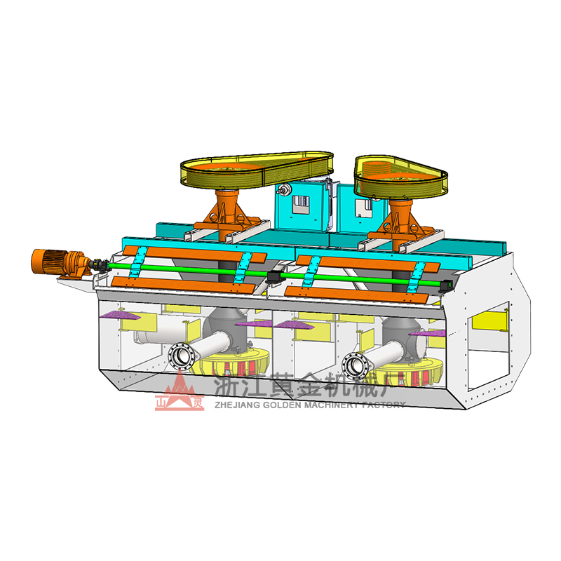 BF Type Self-Aspirated Flotation MachineSelf-aspirating mechanical flotation cell for compact circuits, with integrated air and slurry suction and models from 0.15 to 24 m3.View Product →
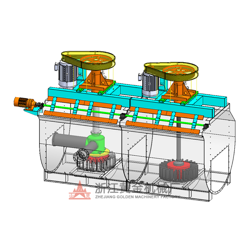 XCF/KYF Flotation Machine SeriesCombined XCFII suction and KYFII direct-current tank design supports horizontal layouts and reduces foam-pump needs in medium-mine return.View Product →
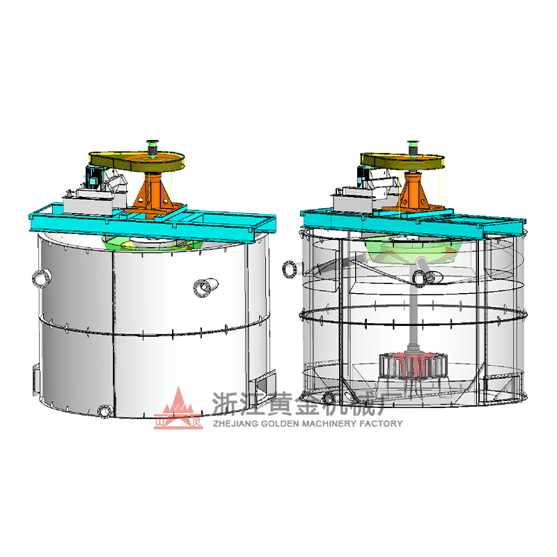 Large Flotation Machines for High-Throughput PlantsHigh-capacity flotation equipment for expanding ore-dressing plants, covering XCF/KYF and CLF models with wide mineral adaptability and resource recovery support.View Product →
Cell type is only one part of the selection. The number of cells in series, the roughing-scavenging-cleaning configuration, the feed particle size distribution and the reagent scheme all influence the final result. A large cell with a short-circuiting feed box will underperform a smaller cell with well-designed baffles and stable pulp flow. A self-aspirated cell with poor air intake maintenance will behave like a badly tuned forced-air cell. The mechanical design must support the metallurgical job.
Reagent Considerations: Collectors, Frothers, Activators, Depressants, pH Modifiers
Reagent selection is where flotation becomes mineral-specific. A collector that works well for one sulphide may be ineffective or unselective for another. A frother that gives a beautiful froth in a copper circuit may be too persistent in a talc-rich or clay-rich feed. The reagent scheme should be built from mineralogy, liberation size, water chemistry and test work, then confirmed in a locked-cycle program before full-scale design. Dosage should be expressed in grams per tonne of dry feed, with clear addition points and conditioning times.
Collectors are usually added in stages. A small amount in the grinding mill or conditioning tank can start the surface reaction, while additional collector in the roughing cell can maintain flotation kinetics. Overdosing collector can increase recovery but reduce selectivity, leading to higher gangue entrainment and difficult cleaning. Underdosing can leave valuable minerals in the tailings, especially coarse or partially liberated particles. Frothers need similar care. Too little frother gives a weak, unstable froth and poor overflow. Too much frother gives a tough froth that is hard to drain and may carry more fine gangue.
| Reagent group | Main role | Practical check |
|---|---|---|
| Collector | Creates hydrophobicity on the target mineral surface. | Confirm dosage by dry tonnage and check stage addition points. |
| Frother | Stabilises bubbles and influences froth texture and drainage. | Match froth life to cell duty; avoid overdosing in cleaner stages. |
| Activator | Prepares a mineral surface for collector attachment. | Check conditioning time and pH before activator addition. |
| Depressant | Reduces flotation of unwanted minerals. | Confirm selectivity in the cleaner circuit, not only in roughing. |
| pH modifier | Controls pulp chemistry and reagent activity. | Measure pH at multiple points; lime addition can drift with feed changes. |
Reagent selection checklist
Start with mineralogy
Identify valuable minerals, gangue minerals, liberation size and coatings. A reagent scheme that ignores mineralogy is only guesswork.
Use stage addition
Split collector and frother addition between conditioning and flotation stages. This gives better control over kinetics and selectivity.
Check water quality
Salinity, hardness and residual reagents can change froth behaviour. Process water changes should be treated as a circuit change.
Confirm in locked cycle
Open-circuit tests can look better than they are. Locked-cycle testing shows the effect of circulating loads and cleaner performance.
Temperature and conditioning time also matter. A collector that needs 8 to 10 minutes of conditioning in one plant may need a different time in another because the ore is finer, the pH is different or the water chemistry interferes. The operator should record dosage, pH, conditioning time and flotation response together. When a reagent change is made, the first question should be whether the change improved selectivity at the target recovery, not simply whether the froth looked better.
Design and Operating Checks Before You Buy
The first purchase question is not “which cell is best?” It is “what duty must this cell perform?” A rougher cell needs different retention, froth handling and wear protection from a cleaner cell. A scavenger cell may need higher mass pull and stronger agitation. A cleaner cell may need deeper froth, wash water and more careful air control. The circuit arrangement should be defined before the cell volume is selected, because the number of stages and the circulating load determine the effective residence time.
Use a simple calculation to sanity-check cell volume. Nominal retention time is cell volume divided by pulp flow. A 100 m³ cell treating 300 m³/h of pulp has about 20 minutes of nominal retention, before accounting for short-circuiting and dead volume. If test work calls for 24 to 30 minutes in roughing, one cell may not be enough, or the circuit may need a different cell arrangement. This calculation does not replace test work, but it quickly shows whether a proposed layout is in the right range.
Throughput and pulp flow
Confirm design tonnage, solids density, pulp flow and the expected range of ore variability. Do not design only for the best ore.
Retention and stage count
Check roughing, scavenging and cleaning retention separately. Each stage has a different job and a different target.
Air and froth control
Confirm blower capacity, air control valves, froth depth adjustment and launder design. These details decide operability.
Wear and maintenance access
Review impeller, stator, tank liner and air pipe access. A cell that is hard to maintain will lose performance over time.
Project references are useful when they match the duty. A circuit that handles zinc flotation with a specific feed and cleaning arrangement can reveal practical issues that a general brochure cannot. The 3,000 t/d zinc flotation technical reform is one example of how cell selection, circuit layout and operating targets are linked in a real project. The useful lesson is not to copy the flow sheet, but to ask which conditions made that flow sheet work and whether your ore and site conditions are similar.
Before placing an order, request a clear scope: cell volume, effective volume, impeller speed, motor power, air requirement, froth overflow arrangement, wear part list, foundation loads and control interface. Ask for the recommended operating range, not only the design point. A flotation circuit that runs well at one feed rate but cannot turndown to 60 percent capacity will create problems during commissioning and market changes. The same applies to ore changes: a circuit that is tuned only for one blend may struggle when the pit moves into a different zone.
Common Operating Problems and Fixes
Most flotation problems show up as a change in froth, mass pull, grade or tailings assay. The operator should first confirm that the feed is stable. A sudden change in grind size, pulp density, pH or reagent flow can look like a cell problem when the cell is only responding to the feed. After feed stability is checked, look at air, froth depth and impeller condition. A worn impeller can reduce air dispersion and solids suspension without any change in set point.
| Symptom | Likely cause | Check first | Practical action |
|---|---|---|---|
| Low recovery | Insufficient collector, low air, short retention or coarse liberation | Tailings assay, air rate, grind size and reagent dosage | Adjust one variable at a time and resample after stabilisation. |
| Low concentrate grade | Entrainment, high froth pull, weak depression or excessive frother | Froth depth, wash water, frother dosage and cleaner circuit load | Increase froth drainage, reduce mass pull or review depressant addition. |
| Unstable froth | Low frother, high pH swing, fine clay or excessive air | Frother flow, pH trend, feed density and air setting | Stabilise feed chemistry before increasing frother blindly. |
| Sanding in the tank | Low impeller speed, coarse feed, high density or worn impeller | Impeller condition, motor current and pulp density | Restore agitation and review feed size distribution. |
| Froth overflowing too fast | High air, high frother or shallow froth depth | Air valve position, frother dosage and froth depth | Reduce air or frother gradually and watch grade response. |
| High reagent consumption | Reagent loss, pH drift, competing minerals or poor addition point | Addition sequence, conditioning time and water quality | Review stage addition and confirm dosage by dry tonnage. |
One common mistake is to correct a grade problem by adding more depressant before checking froth depth and wash water. Another is to raise collector dosage when the real issue is insufficient liberation. A quick particle size check can save a lot of reagent. If the target mineral is still locked with gangue, no flotation cell can separate it cleanly. The practical response may be a grinding change, a re-grind step or a different circuit configuration, not a higher reagent dose.
Mechanical checks deserve the same attention as chemical checks. Air pipes can scale or block. Impellers can wear unevenly. Stator gaps can open. Froth launder lips can become uneven. A cell that has lost its air dispersion will often show a flat froth and high tailings losses even when the control panel looks normal. A monthly inspection that records impeller clearance, air pipe condition, froth depth setting and motor current can reveal drift before it becomes a metallurgical problem.
What to Include in a Flotation Test and Scale-Up Program
A useful flotation test program begins with a representative sample and a clear question. Is the objective to confirm reagent selection, compare cell types, estimate retention time or predict cleaner performance? The sample should represent the expected feed, including the range of oxidation, alteration and liberation that the plant will see. A single high-grade sample can give an optimistic result that is difficult to reproduce at full scale.
Mineralogy should be completed before or alongside the flotation tests. It identifies the target minerals, their association with gangue, the liberation size and any coatings or slimes that may interfere with collector action. Without mineralogy, reagent selection becomes a trial-and-error exercise. With mineralogy, the test worker can choose a collector family, pH range and depressant strategy with a defensible starting point.
- Open-circuit tests to establish roughing and scavenging response.
- Locked-cycle tests to show the effect of circulating loads and cleaner performance.
- Reagent dosage tests with stage addition and controlled conditioning time.
- Grind size tests to find the liberation size that gives the best recovery-grade balance.
- Water quality tests where salinity, hardness or residual reagents are variable.
- Pilot or semi-industrial runs when the circuit is new, the ore is complex or the scale-up risk is high.
Scale-up should include more than cell volume. Air rate per unit volume, froth depth, impeller tip speed, residence time distribution and launder capacity all affect the result. A cell that performs well in a laboratory cell may behave differently when the froth phase becomes deeper and the pulp flow pattern changes. The design team should ask how the proposed cell will be controlled, sampled and maintained. A circuit with good instrumentation and clear sampling points is easier to optimise than one that relies on visual judgement alone.
Commissioning should include a baseline survey. Record feed rate, density, pH, reagent flows, air settings, froth depth, motor current and assay results for every stage. That baseline becomes the reference for later troubleshooting. When a problem appears months later, the team can compare the current froth and assay profile with the original survey instead of guessing. This is especially useful when ore blends change or when a new operator takes over the circuit.
FAQ
What is the main principle of a flotation machine?
The main principle is selective bubble attachment. Hydrophobic particles attach to air bubbles and rise into a froth, while hydrophilic particles remain in the pulp and leave as tailings. The cell provides air dispersion, agitation, residence time and froth removal.
How do I choose between a self-aspirated and a forced-air flotation cell?
Use test work and circuit duty to decide. Self-aspirated cells are simple and suit many roughing and scavenging duties. Forced-air cells give more control in deeper tanks and larger volumes. The final choice should consider air control, maintenance access, feed stability and the required operating range.
Why does froth depth affect concentrate grade?
Froth depth affects drainage time. A deeper froth allows more gangue to drain back to the pulp and can improve grade, but if it is too deep or too stable it may reduce mass pull and recovery. Adjust froth depth with assay and mass pull data, not appearance alone.
How much reagent should be added?
Dosage should come from test work and be expressed in grams per tonne of dry feed. Add reagents in stages and check pH, conditioning time and water quality. A dosage that works in one circuit may fail in another because mineralogy and pulp chemistry are different.
Can a flotation machine fix poor liberation?
No. Flotation can only separate particles that are sufficiently liberated and have the right surface chemistry. If the target mineral is locked in gangue, the circuit may need finer grinding, a re-grind step or a different flow sheet before flotation performance can improve.
What should be inspected during routine maintenance?
Inspect impeller and stator wear, air pipes, froth launder lips, tank liners, drive components and control valves. Record motor current and air pressure. A small mechanical drift can reduce air dispersion and cause tailings losses before it is visible in the control room.
When is a large flotation machine the better choice?
A large cell can reduce the number of units, simplify the layout and lower operator attention per unit. It is most suitable when the feed is stable, the circuit is well controlled and maintenance access is planned. It is not automatically better for every duty, especially where flexibility or frequent ore changes are important.


