
 EN
 English
 русский
 简体中文


The Four Duty Points That Decide Plant Stability
A flotation circuit is only as stable as the feed it receives. The crushing station must deliver a consistent top size, the grinding circuit must hold a target liberation size, the classifier must return coarse particles without sending slimes forward, and the flotation bank must keep pulp density, pH and air within narrow bands. When one duty point drifts, the others compensate with more reagent, more power or lower recovery. Those costs appear in the monthly report, but they usually originate upstream.
Check closed-side setting, screen aperture and tramp-metal protection. A coarse surge in mill feed raises power draw without raising liberation.
Confirm with sieve analysis, not with motor current alone. The target depends on mineral liberation and downstream flotation kinetics.
Match the cut point to the liberation size. Too coarse sends unliberated particles forward; too fine creates slimes and reagent waste.
Verify with testwork and plant survey. Residence time without stable pulp density and air control is only a nominal number.
These are starting ranges, not guarantees. A copper porphyry, a lead-zinc skarn and a spodumene pegmatite may share the same flowsheet labels but require different crush sizes, grind targets and flotation chemistry. The practical rule is simple: size the crushing, grinding and classification train around the flotation circuit’s true capacity, then confirm every number with locked-cycle testwork and a commissioning survey.
Process Flow Map: Crushing, Grinding, Classification, Flotation
The flow is often drawn as four boxes. In operation it is a chain of six control points: crusher setting, screen aperture, mill feed rate, mill discharge density, classifier overflow fineness and flotation pulp level. Each control point has a measurable target and a predictable failure mode. The layout below shows the basic sequence and the variables that matter most.
In a 1,000 t/d plant, a two-hour shutdown in the crushing section can leave the mill with a coarse stockpile that takes most of a shift to correct. In a 10,000 t/d plant, a 2% drift in classifier overflow fineness can change flotation recovery before the control room notices. The difference is not the flowsheet drawing; it is the surge capacity, instrumentation and operating discipline around each stage.
| Stage | Typical equipment | Main control | Common failure | Procurement check |
|---|---|---|---|---|
| Crushing | Jaw or gyratory primary; cone secondary and tertiary; vibrating screen | Closed-side setting, screen aperture, feed moisture | Flaky feed, worn liners, blocked chute | Reduction ratio, throughput at design CSS, tramp-iron protection |
| Grinding | Wet grid ball mill, rod mill, mill discharge sump | Mill power, ball charge, pulp density, feed size | Overloading, poor liner profile, unstable feed | Installed power, liner material, trunnion and bearing design |
| Classification | Spiral classifier, hydrocyclone, vibrating screen | Overflow fineness, sand return, circulating load | Coarse overflow, worn spiral, cyclone blockage | Cut point at design density, wear life, ease of adjustment |
| Flotation | Rougher, scavenger, cleaner cells; reagent and air systems | Pulp density, pH, air rate, froth depth, reagent dosage | Unstable froth, poor air dispersion, reagent imbalance | Cell volume, impeller speed, air supply, launder design |
The table is deliberately short because every ore body changes the numbers. What does not change is the need to define a measurable target for each stage and to check it during commissioning, not after the first month of production. The next three sections deal with the stages that most often set the ceiling on flotation performance.
Crushing: Set the Feed Size Before You Buy the Mill
Crushing is often treated as a necessary step before grinding. In practice it is the first stage of liberation control. A jaw crusher set too wide sends more work to the ball mill; a cone crusher with a worn mantle produces a wider product curve; a screen with blinded apertures recirculates fines that should already be finished. The ball mill then absorbs the variation as higher power draw, lower throughput or a coarser grind.
Primary and secondary reduction
For hard rock, a jaw crusher is a practical primary choice when the mine plan delivers run-of-mine feed with moderate clay content. A gyratory crusher is preferred for high capacity and continuous feed, but it demands a more substantial foundation and a more controlled dump arrangement. The primary setting should be checked against the largest lump size, the reduction ratio and the downstream secondary feed opening. A typical primary reduction ratio of 3–6 is not a target to push; it is a limit to respect.
Secondary crushing usually uses a standard cone crusher in open or closed circuit. The key procurement question is not only the nominal capacity but the capacity at the required closed-side setting. A crusher rated at 300 t/h with a 40 mm setting may deliver far less at 20 mm. Ask for the capacity curve, the power draw at that setting and the recommended liner profile. If the supplier cannot provide those three items, the quotation is incomplete.
Tertiary crushing and screening
Tertiary crushing with a short-head cone and a closed-circuit screen produces a mill feed that is easier to grind and more consistent in size. A common target is 80% passing 10–12 mm, but the right number depends on the mill diameter, ball size and ore hardness. Pre-screening before tertiary crushing removes finished material and reduces unnecessary size reduction. It also lowers the risk of packing and improves the screen’s efficiency.
A 3 mm drift in closed-side setting may look small on paper, but it can shift the mill feed curve enough to change throughput. Confirm the adjustment mechanism and wear allowance.
Screen media, aperture condition and support structure determine the final feed size. A good crusher with a blinded screen still sends coarse material to the mill.
A metal detector and magnet before the tertiary crusher are cheap compared with a broken mantle, a bent shaft or a week of lost production.
Do not size the ball mill around the crusher’s best day. Size it around the feed curve the crusher can hold on a normal shift, with worn liners and realistic moisture. That approach usually produces a more conservative mill selection and fewer surprises during ramp-up.
Grinding: Power, Residence Time and the P80 You Can Hold
Grinding is the largest power consumer in most concentrators, so it attracts attention. The more useful question is not “how large is the mill?” but “what P80 can the circuit hold under production conditions?” A wet grid ball mill with the right ball charge, liner profile and speed can deliver a stable product, but it cannot correct an unstable feed or a poorly sized classifier.
Ball charge typically starts around 35–45% of mill volume, depending on the manufacturer’s recommendation and the ore. Mill speed is usually set between 65% and 78% of critical speed. Higher speed increases impact and power draw, but it can also increase wear and produce more fines. The liner profile changes the charge motion as it wears; a new liner and a worn liner are not the same operating machine.
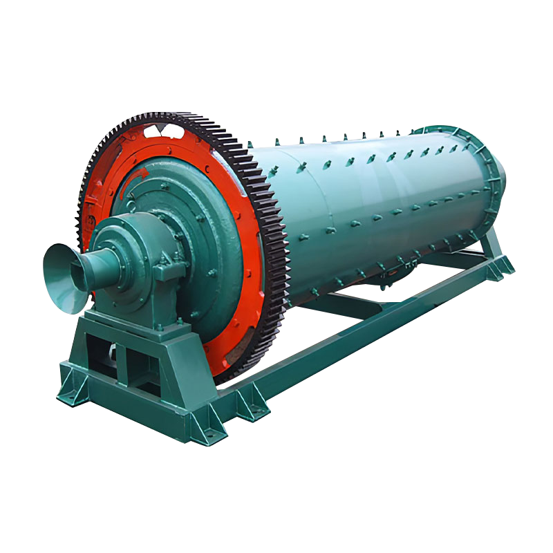 Wet Grid Type Ball Mill for Coarse-to-Mid GrindsFor circuits needing robust discharge and a target P80 around 75–150 µm, this wet grid ball mill offers timely slurry discharge and reduced over-grinding.View Product →
A wet grid ball mill is often a practical choice when the circuit needs a robust discharge, simple operation and a target P80 between roughly 75 and 150 µm. For coarser grinds, a rod mill may be considered; for finer grinds, a larger ball mill or a closed-circuit arrangement may be necessary. The decision should be based on testwork, not on a single rule of thumb.
Grinding circuit stability depends on three measurements: mill feed rate, mill discharge density and classifier overflow fineness. If the feed rate rises without a corresponding change in water addition, the pulp becomes too dense, the mill retains material longer, and the classifier may overflow coarser. If the feed rate falls, the circuit may over-grind, producing slimes that consume reagents and reduce flotation selectivity. The control system should trend all three measurements together.
What a grinding survey should show
- Mill power draw at steady feed rate, with the ball charge and liner condition recorded.
- Feed and discharge particle size distributions, not only a single P80 value.
- Pulp density at mill discharge and at classifier overflow.
- Circulating load calculated from fresh feed and classifier sand return.
- Water addition points and response time after a set-point change.
A copper-gold pyrite project in Anhui illustrates why the grind target must follow the mineralogy. The circuit cannot be optimized around a single number copied from another plant; it has to be tuned to the liberation characteristics of the ore. The same principle applies to polymetallic ores, where a coarse grind may liberate the primary valuable mineral while leaving associated minerals locked.
For project planning, ask the mill supplier for the recommended ball charge, liner material, trunnion bearing type, lubrication system and expected power draw at the design P80. Also ask for the maximum feed size the mill can accept and the size distribution it expects from the crushing circuit. Those details prevent a common procurement error: buying a mill that is mechanically adequate but hydraulically or metallurgically mismatched to the feed.
Classification: The Cut Point That Protects Flotation
Classification separates the mill discharge into a fine overflow that goes to flotation and a coarse sand that returns to the mill. The cut point is the practical boundary between “finished” and “recycle.” If the cut point is too coarse, unliberated particles enter flotation and depress recovery. If the cut point is too fine, the circuit over-grinds, generates slimes and wastes power. The operating target should come from liberation testwork and flotation response, not from a default setting.
A spiral classifier is common in smaller and medium-sized circuits because it is robust, easy to observe and tolerant of fluctuations. It uses a settling tank and a rotating spiral to transport coarse sand back to the mill. A hydrocyclone is more compact and can achieve a finer cut, but it is less forgiving of unstable feed density and coarse trash. The choice depends on capacity, target fineness, wear life and the available layout.
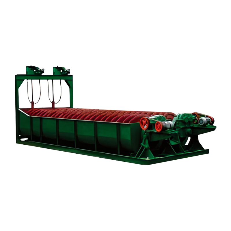 Spiral Classifying Equipment for Closed-Circuit MillingFor coarse overflow, high sand return and simple maintenance, this spiral classifier returns coarse sand to the mill in closed circuit.View Product →
A spiral classifier is often suitable when the target overflow is relatively coarse, the circuit needs high sand return and the plant values simple mechanical maintenance. For finer cut points and higher throughput, a cyclone cluster may be preferred, but it requires a dedicated feed pump, stable pressure and a proper apex and vortex finder selection. In either case, the classifier should be sized on circulating load, not only on fresh feed.
Classification signals to watch
The cut point is too coarse or the feed density is too high. Check spiral wear, weir height and water addition before changing the mill.
Circulating load may be excessive. Confirm the fresh feed rate and the classifier’s actual capacity at the operating density.
The circuit may be over-grinding. Check whether the mill is running below design feed rate or whether the classifier is returning too little coarse material.
Slimes from over-grinding can consume reagents and change froth structure. Review the full particle size distribution, not only the P80.
The 1,400 t/d zinc ore dressing project in Inner Mongolia is a useful reminder that classification and flotation must be commissioned as one system. A classifier that meets its overflow target on a clean water test may behave differently with viscous pulp, altered density and worn parts. Survey the classifier under production load, then adjust the flotation reagent scheme to the actual particle size distribution.
For procurement, request the classifier’s capacity curve at the design overflow fineness, the spiral diameter and pitch, the wear material, the bearing arrangement and the recommended installation slope. For cyclones, request the apex and vortex finder options, the pressure range and the expected wear life. These details matter more than a generic capacity figure.
Flotation: Rougher, Scavenger and Cleaner Are Different Duties
Flotation is not a single unit operation. A rougher bank is a bulk removal machine; a scavenger bank recovers values from the rougher tail; a cleaner bank improves grade by rejecting entrained gangue. Using the same cell type and the same operating target for all three duties is a common commissioning mistake. The rougher needs enough residence time and air to float the valuable minerals. The cleaner needs a stable froth, controlled pulp level and often a different reagent addition strategy.
Typical rougher residence time is 8–15 minutes, but the number depends on mineral kinetics, particle size and pulp density. Scavenger residence may be longer because the remaining particles are slower to float. Cleaner residence is often shorter, but cleaner circuits are more sensitive to fluctuations. A cleaner that receives a variable rougher concentrate will produce a variable final grade, no matter how well the cleaner cells are adjusted.
Reagent and pulp chemistry
Collector dosage, frother type and dosage, activator or depressant addition, pH and pulp density all interact. A small change in pH can change the surface charge of the mineral and the action of the collector. A change in frother can alter bubble size and froth stability. The practical approach is to establish a baseline with plant survey data, then change one variable at a time and allow the circuit to reach steady state before judging the result.
Pulp density in flotation usually sits between 25% and 40% solids, depending on the ore and the stage. Too dense, and air dispersion and froth transport suffer; too dilute, and residence time and reagent concentration become difficult to control. The target should be set with the cell manufacturer’s volume calculation and confirmed by a residence time distribution test if the circuit is critical.
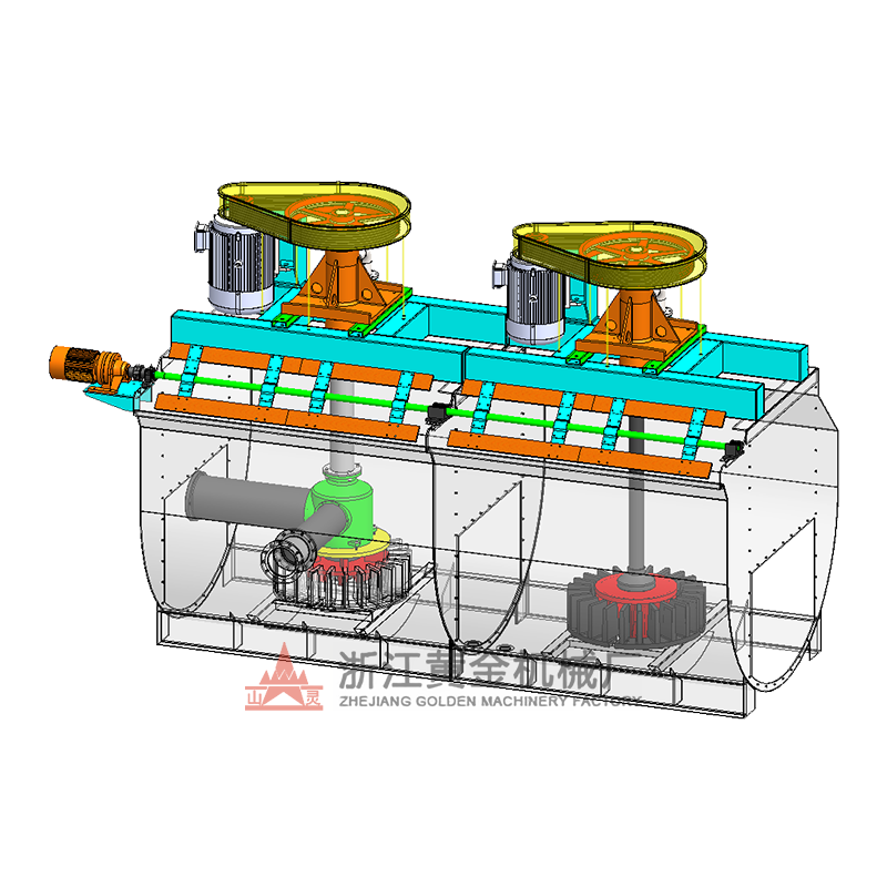 XCF/KYF Flotation Machine for Rougher and Cleaner DutyFor flotation circuits needing effective air dispersion and stable pulp circulation, the XCF/KYF configuration combines suction and direct-current tanks for flexible cell layout.View Product →
Cell selection should follow duty. For a rougher duty with high pulp volume, a large flotation machine can reduce the number of units and simplify the launder layout. For a cleaner duty, smaller cells may give better froth control and selectivity. The XCF/KYF type flotation machine is one option for circuits that need effective air dispersion and a stable pulp circulation pattern. BF, JJF and SF types each have their own place, but the selection should be based on testwork, cell volume, air requirement and maintenance access.
Flotation control variables
- Pulp level: maintain a stable froth depth and avoid sudden level changes that push gangue into the concentrate.
- Air rate: match air addition to cell volume and froth carry rate; too much air can create unstable froth.
- pH: control within the range established by testwork; pH excursions can reverse selectivity.
- Reagent dosage: use staged addition where possible and verify dosage by flow meter, not by pump setting alone.
- Particle size: a coarse or fine shift from classification changes flotation kinetics and reagent demand.
A flotation circuit can recover well on one day and lose several percentage points the next without any change in the cell. The cause may be a coarser grind, a higher circulating load, a reagent preparation error or a change in ore blend. The control room should have a short list of leading indicators, not only a recovery target at the end of the shift.
Layout, Instrumentation and Commissioning: Where Projects Lose Time
A good flowsheet can still underperform if the layout creates unstable feed, the instrumentation is inadequate or the commissioning sequence is rushed. Layout affects residence time, launder slope, sump capacity and maintenance access. Instrumentation affects what the operators can see and correct. Commissioning determines whether the plant reaches design capacity in weeks or months.
Launders should be sized for the maximum froth volume, not the average. A launder that runs full on a good day will overflow on a surge. Sumps should have enough working volume to absorb a normal feed interruption without sending a density wave to flotation. Piping should avoid sharp bends and unnecessary vertical lifts that can cause settling or air entrainment. Maintenance access should allow liner changes, impeller inspection and cell interior cleaning without dismantling adjacent equipment.
The chart is qualitative, not plant data. It reflects a common pattern: feed size and pulp density cause more commissioning delays than reagent selection, because they are upstream variables that affect every downstream decision. A plant that can hold a steady grind and density will usually tune reagents faster than a plant that is still fighting coarse feed.
Commissioning sequence that reduces rework
- Dry commissioning: check rotation, lubrication, guarding, interlock logic and emergency stops.
- Water commissioning: confirm pump curves, valve response, launder flow and sump levels.
- Crushing circuit: run with screened feed, verify CSS and screen performance, then build a stockpile.
- Grinding circuit: run at reduced feed, establish ball charge and water balance, then raise to design load.
- Classification circuit: verify overflow fineness and sand return at steady feed before flotation is started.
- Flotation circuit: commission cells with water and air, then introduce pulp at low density and raise gradually.
- Reagent system: calibrate pumps and confirm dilution, mixing and dosing response before relying on set points.
- Performance test: run a minimum eight-hour steady-state survey and compare with the design basis.
Do not commission the flotation bank before the grinding circuit can hold a steady P80 for at least eight hours. A flotation circuit fed by a fluctuating grind will produce data that cannot separate cell performance from upstream instability. The same applies to classification: if the overflow fineness is still moving, the flotation reagent scheme is being tuned against a moving target.
Procurement, Spares and Shop Testing: What to Lock Down
Equipment selection is only half of the project. The other half is the specification, inspection and spare-parts plan that determines whether the plant can stay online. A ball mill, flotation cell or classifier is a long-life asset, but its availability depends on wear parts, lubrication and the ability to replace components without a major shutdown.
Confirm installed power, speed, bearing type, lubrication, liner material, connection dimensions and expected wear life. Ask for the calculation basis, not only the model number.
Define capacity, feed size, product size, recovery or grade targets and the testwork basis. A guarantee without a testwork basis is difficult to enforce.
Request shop assembly records, run tests, dimensional reports and material certificates. For critical drives, witness the no-load run and check vibration and temperature.
Include liners, impellers, stators, shafts, bearings, seals, wear plates and control valves. Identify long-lead items before shipment, not after the first failure.
For a flotation cell, the impeller and stator are the parts most likely to affect performance as they wear. A worn impeller can reduce air dispersion and change the pulp circulation pattern, even if the motor current looks normal. For a classifier, the spiral, lower bearing and wear shoes deserve attention. For a ball mill, liner profile, trunnion bearings, lubrication and the feed and discharge arrangements are the main availability items.
A manufacturer with machining, assembly and test capability can shorten the path from drawing to commissioning. It can also provide a more coherent spare-parts package because the same workshop controls the tolerances, material traceability and assembly records. The practical procurement question is not only “who can supply the equipment?” but “who can support the installation, commissioning and wear-part replacement without breaking the process guarantee?”
Shipping and site planning also matter. Large mill shells, trunnion assemblies and flotation cell tanks need lifting points, foundation bolts and access routes that match the site. Confirm the shipping dimensions, the heaviest lift, the anchor-bolt layout and the foundation load before the equipment leaves the shop. A late foundation change can cost more than the equipment itself.
FAQ: Ore Beneficiation Process Flow
What is the purpose of crushing before grinding?
Crushing reduces run-of-mine ore to a size the grinding mill can accept efficiently. It also improves feed consistency and reduces the energy required for grinding. The target is not the smallest possible product; it is the most stable feed curve the mill and classifier can handle.
How fine should the grind be for flotation?
The grind should be fine enough to liberate the valuable minerals without over-grinding the gangue. A common starting range is 65–80% passing 75 µm, but the correct target must come from mineral liberation analysis and flotation testwork. Some ores require a coarser grind; others need a finer one.
Should I use a spiral classifier or a hydrocyclone?
A spiral classifier is robust and suited to coarser cut points and simpler circuits. A hydrocyclone is compact and can achieve finer cut points, but it needs stable feed pressure and density. The choice depends on capacity, target overflow fineness, wear life and layout.
Why does flotation recovery drop even when reagent dosage is unchanged?
Recovery can fall because the feed size changed, pulp density drifted, pH moved, air rate changed or the ore blend shifted. Reagent dosage is only one variable. Check the grinding and classification performance before adjusting the flotation circuit.
What is a reasonable circulating load for a ball mill circuit?
A common range is 250–350%, but the right value depends on the ore, mill size, classifier performance and target grind. Higher circulating loads can improve classification efficiency but increase pumping and wear. Confirm the design value with testwork and plant survey data.
What should be included in a commissioning survey?
Record feed rate, particle size distributions, pulp density, mill power, classifier overflow fineness, circulating load, flotation pH, air rate, froth depth, reagent dosages and stage recoveries. A survey without those measurements cannot separate equipment limitations from operating adjustments.


